The IEC 61400-1 turbine safety standard
You may have heard that IEC defines wind turbine classes with labels like IIIB, where the roman number refers to a reference wind speed and the index letter refers to a turbulence category. To verify that a wind turbine belongs to a give wind turbine class, it must be proven safe under a set of predefined load cases. Each load case is specified by combinations of mode of turbine operation, wind conditions, and load type. Examples of modes of operation are normal operation, idling, and operation with yaw error. Wind conditions are specified by extreme wind speed, vertical wind shear, flow inclination, turbulence and rare gust-like events. The load type is either an ultimate load, which might instantly damage the turbine, or a fatigue load.
Turbine designers will typically model turbine vibrations and dynamic forces on critical components by aeroelastic simulation programs such as HAWC2. Depending on the load case, the wind interacting with the turbine is either deterministic or a pseudo-random wind field with realistic turbulence characteristics. Aeroelastic simulations are processed for all IEC load cases, and turbine safety is verified for each of the deterministic load cases. In addition, the accumulated fatigue damage caused by stochastic forcing is evaluated for a design life time of twenty years and compared to the material strength. Wind load models are scaled differently for each wind turbine class, thus a class IA turbine is tested for higher extreme wind speed and more severe turbulence than a class IIB turbine.
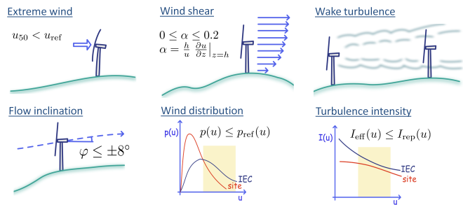
The siting engineer must verify the safety of the deployed turbines. In principle, the aeroelastic simulation could be repeated with local wind conditions at specific turbine positions. It is, however, simpler to apply the site-assessment rules specified in another chapter of IEC 61400-1. Here, the main principle is that local wind conditions must not exceed those of the models used for turbine classification. This imposes simple limits on fifty-year extreme wind, flow inclination and wind shear, see Figure 1, whereas turbulence assessment is more complicated.
Variable atmospheric stability, unsteady wind, and directional variation of upwind terrain will introduce variations in observed turbulence intensity. Material damage has a highly non-linearly relation to load amplitudes and thus to turbulence intensity, so a few situations with extreme turbulence may cause most of the fatigue damage. Therefore, the IEC standard applies a representative turbulence intensity for turbine classification, which is defined as a high percentile of the expected natural variation. This variation will generally decrease with wind speed, and the IEC normal turbulence model (NTM) accounts for this effect.
Unlike the NTM turbulence model, site-specific turbulence usually depends on wind direction. To facilitate comparison with the NTM model, the IEC standard suggests the so-called effective turbulence intensity, which is an ideal turbulence independent on wind direction and expected to cause the same fatigue damage as variable turbulence in winds from all directions. The effective turbulence intensity includes added turbulence from wakes of neighbour turbines, and a simple wake turbulence model is provided. Effective turbulence intensity will generally decrease with wind speed due to decreasing stability effects and turbine thrust coefficient.